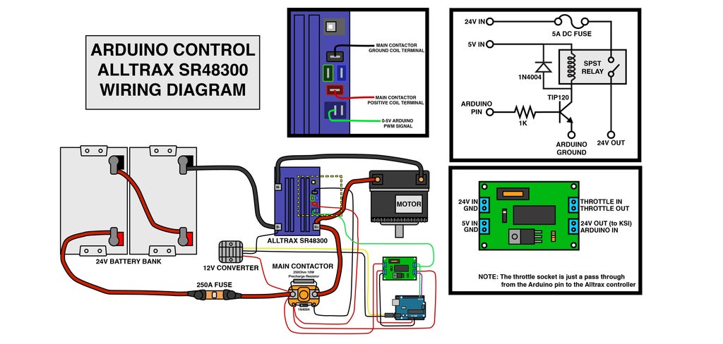
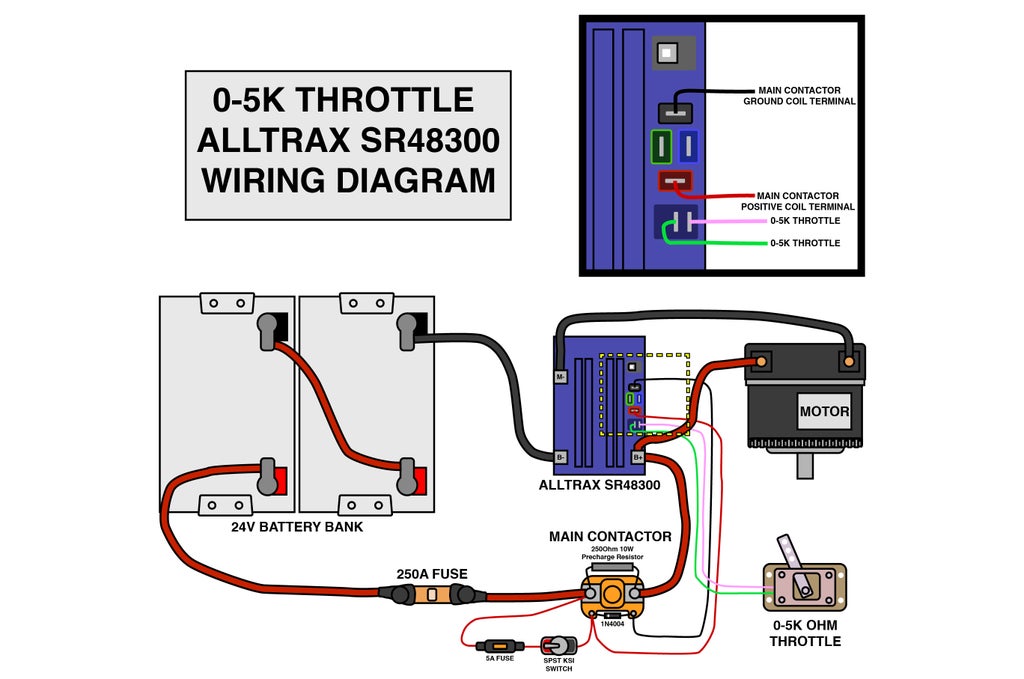
Kb Electronics Kbwc 15 Wiring Diagram
Ground wire is not counted when designating 23 or 4 wire controls. FUSE SELECTION CHART HORSEPOWER 90 VDC Motor 180 VDC Motor Approx.

Yamaha Blaster Wiring Diagram Kill Switch Wiring Diagram Diagram
KBWC-15L 4L Adds DPDT OnOff Switch 4-wire control Model KBWC-25 only.

Kb electronics kbwc 15 wiring diagram. Kbwc 15 Wiring Diagram wiring diagram is a simplified adequate pictorial representation of an electrical circuit. Click Add to Cart to buy KB Electronics H9000C 5A Variable Speed Control 115V. Permanent Magnet PM Type.
The KBWC-18K is a Solid State AC Motor Fan Speed Control designed for 2 X 4 electrical wall box installation. Includes individual packaging with dial plate knob mounting screws wire connectors and instructions. KB Electronics Model KBWC-15K UL Variable Speed Fan Control Wall Mount Rated 50 Amps 120 VAC for use with Shaded Pole and PSC Motors 16 2101 21.
MINIMUM SUPPLY WIRE SIZE REQUIREMENTS Minimum Size Wire AWG Cu Only Maximum Motor Current DC Amps Maximum Motor HP 90 V Maximum Motor HP 180 V Max 50 Foot Run Max 100 Foot Run 6 05 1 16 14 12 1 2 14 12 16 15 3 12 12 Minimum recommended wire size. 01 KB Electronics 8811005 Dial-A-Temp Fan Speed Control 57. KB Electronics offers 21 Wall Mount AC Motor Fan Speed Controls ready for distributions.
Connect half voltage field wires 90 volt motors with 50 volt fields and 180 volt motors with 100 volt fields to F1 and L1. IV C on page 11. E 32006 Ground wire is not counted when designating 23 or 4 wire.
KBWC-25 4L NS Omits OnOff Switch. KBWC-110K 10A Variable Speed Control 115V. 15 Amp Plug 125V 5-15P Nylon BlackWhite Industrial Grade More 0 KB Electronics KBWC-110K 10A Variable Speed Control 115V.
The KBWC-15K is a Distributor packaged Solid State AC Motor Speed Fan Control. 11 AC LINE INPUT CONNECTION Wire the AC line input to Terminal Block TB1. SPEED OR TORQUE MODE.
Be sure jumper J3 is set to the proper position 90V for 90 volt DC motors and 180V for 180 volt DC. The rated AC line voltage of the drive must match the actual AC line input voltage. The KBWC-16K is a Distributor packaged Solid State AC Motor Speed Fan Control.
Shunt field wires 90 volt motors with 100 volt fields and 180 volt motors with 200 volt fields to F1 and F2. Be sure jumpers J2A and J2B are both set to the correct input line voltage 115 or 230 VAC. KBWC-15K L Adds auxiliary lead 3-wire control.
It operates from 115 VAC 5060 Hz and has a maximum rating of 50 Amps 40C. Do not wire this drive to a GFCI. AC Line Wire AC line voltage to terminals L1 and L2.
CONNECTION DIAGRAM FOR 2-WIRE CONTROLS SWITCH MODELS TRIAC SWITCH CONTROLLED LOAD AC LINE. Supplied standard on all models rated 8 Amps and above. KBEH9000C KBEKBWC15K KB Electronics H9000C Variable Speed Controls Controls Switches Fans.
It operates from 115 VAC 5060 Hz and has a maximum rating of 80 Amps 40C. For help with 5A Variable Speed Control 115V from KB Electronics. KBWC-25 4L NS Omits OnOff Switch.
It operates from 115 VAC 5060 Hz and has a maximum rating of 60 Amps 25C. If operation with a GFCI is required contact our Sales Department. The KBWC-18K provides infinitely variable speed motor control for Shaded Pole Permanent Split Capacitor and Universal ACDC motors.
The KBWC-15K provides infinitely variable speed motor control for Shaded Pole Permanent Split Capacitor and Universal ACDC. Connect ground wire earth to green ground screw on case. Includes individual packaging with dial plate knob mounting screws wire connectors and instructions.
Supplied standard on all models rated 8 Amps and above. Kbwc 15 Wiring Diagram. The KBWC-16K provides infinitely variable speed motor control for Shaded Pole Permanent Split Capacitor and Universal AC.
It is designed for mounting in a 2 X 4 electrical wall box. Jumper J1 is factory set for speed control operation SPD. KBs four 4 Chassis Mount Fan Speed Controls provide infinitely.
It is designed for mounting in a 2 X 4 electrical wall box. Wire-Cuts can take 1-2 business days to ship. KBWC-16C K Mounting Kit.
KBWC-15L 4L Adds DPDT OnOff Switch 4-wire control Model KBWC-25 only. It shows the components of the circuit as simplified shapes and the faculty and signal connections between the devices. KB standard off-the-shelf DC Drives available in a NEMA 4X IP65 aluminum enclosure.
KBWC-15K L Adds auxiliary lead 3-wire control. Connect motor armature leads to A1 and A2. KBs AC drives provide variable speed for 3ph AC Induction motors from 18 through 1 horsepower.
See Section 51 on pages 13 14.

Acme Ranco Speed Control Switch Mcf 611132 001 6 Fla 12 Lra 120 Vac Nos For Sale Online Ebay

Acme Ranco Speed Control Switch Mcf 611132 001 6 Fla 12 Lra 120 Vac Nos For Sale Online Ebay

Controlling Motor Speed 16 Steps Instructables

Speed Control Industrial Motor Speed Controls For Sale Ebay

Controlling Motor Speed 16 Steps Instructables

Controlling Motor Speed 16 Steps Instructables

Mercury Outboard Wiring Harness Color Code Google Search Mercury Outboard Outboard Wiring Diagram

Controlling Motor Speed 16 Steps Instructables

5 Watt Fm Amplifier Amplifier Watt Diy Electronics

Controlling Motor Speed 16 Steps Instructables

Nib New Solid State Motor Speed Control By Lennox Model Kbwc 13bv Blue 120v Ebay

Acme Ranco Speed Control Switch Mcf 611132 001 6 Fla 12 Lra 120 Vac Nos For Sale Online Ebay

Acme Ranco Speed Control Switch Mcf 611132 001 6 Fla 12 Lra 120 Vac Nos For Sale Online Ebay

Acme Ranco Speed Control Switch Mcf 611132 001 6 Fla 12 Lra 120 Vac Nos For Sale Online Ebay


