Siemens Tri R Wiring Diagram
The relay and contact device input for Model TRI-R are. This NEW Siemens TRI-R Module Siemens part 500-896224 is an Intelligent RelayMonitoring Interface Module for use in MXLMXLVMXL-IQ fire-alarm control panels FACP.

Tvs Apache Wiring Diagram Dolgular Com At In Tvs Apache Wiring Diagram In 2021 House Wiring Wiring Diagram Electrical Panel Wiring
If you require a Distributor account please contact your Siemens Sales Rep or if you already have a distributor account please contact your Customer Manager for a user account.
Siemens tri r wiring diagram. N I V A H S E I T I R O H T U A S R E L L A T S N I S R E S U O T E C I T O N S E I T R A P D E V L O V N I. Power Limited Wiring In compliance with NEC Article 760 all power limited fire protective signaling. Only TRI-B6 TRI-S TRI-B6R TRI-R and TRI-B6D TRI-D can be used as security initiating devices.
See CSG-M Programming Manual PN 315-090381. XTRI-R - Single Input Mon Modular with Relay Isolator. Integral single-pole double-throw SPDT relay up to 4 amps Model TRI-R.
TRI-R output must be programmed in CSG-M to transfer on loss of AC Mains. Siemens Tri R Wiring Diagram To properly read a wiring diagram one provides to know how the components within the system operate. WIRING INSTRUCTIONS Refer to the wiring diagrams in Figures 2 and 3 and wire the addressable interface module according to the appropriate operation for your system.
POWER LIMITED WIRING FOR TRI-R ADDRESSABLE INTERFACE MODULE In compliance with NEC Article 760 all power limited. Program the H TRI to the desired address. For Remote Station provide 60 hour battery capacity.
FS-TRI-R Control Module Barrier TABS FACE OUT Use PN 330-096393 for Double Gang Box Use PN 330-096384 for 4-inch Switchbox 7 6 7 _ _. Mounts in a 4-square 2-18-deep standard or double-gang box. The H TRI can now be installed and wired to the.
Ref er to Figur e 3 Follo w the instructions in the DPU Manual PN 31 5-033260 to. The TRI-R is designed to monitor a normally open NO dry contact. The interface module reports the status of.
Refer to the appropriate wiring diagram below and wire the addressable interface module accordingly. Refer to System wiring Diagram in this manual. XTRI-R - Single Input Mon Modular with Relay.
Located on the HTRI front panel. When you make use of your finger or perhaps the actual circuit with your eyes it is easy to mistrace the circuit. UL 1076 requires a Model TSW-2 tamper switch and a TSP.
TRI-S and TRI-R are designed to monitor a normally open NO dry contact. The interface module reports the contacts status to the FACP. The interface module reports the contacts status to the control panel.
The Siemens Mode HTRI-series intelligent interface modules are available in three 3 types. The sole purpose of Model TRI-S is to monitor and report the status of the contact while Model TRI-R incorporates an addressable Form C relay. POWER LIMITED WIRING FOR TRI-R ADDRESSABLE INTERFACE MODULE In compliance with NEC Article 760 all power limited.
Refer to the appropriate wiring diagram below and wire the addressable interface module accordingly. WIRING Refer to Figures 4 -9 Refer to the appropriate wiring diagram below and wire the addressable interface module accordingly. The interface module reports the contacts status to the FACP The Siemens TRI-R incorporates an addressable Form C relay.
The interface module reports the contacts status to the FACP. The Siemens 500-896224 TRI-R relay and contact device input are controlled at. Model HTR I-D -DZ as well as Models HTRI-S -SZ and HTRI-R -RZ which are both designed to monitor a NO or NC dry contact.
0 0 . The MMB-2 must be programmed by the CSG-M for all System configurations. Print the cabling diagram off and use highlighters to be able to trace the signal.
The TRI-R is designed to monitor a normally open NO dry contact. 18 AWG minimum 14 AWG maximum POWER LIMITED WIRING FOR THE TSM-1 TEST SWITCH MODULE In compliance with NFPA 70National Electrical. 18 AWG minimum 14 AWG maximum Wire larger than 14 AWG can damage the connector.
For instance if a module is usually powered up also it sends out the signal of 50 percent the voltage plus the technician will not know this hed think he provides an issue as he would expect a 12V signal. The Siemens TRI-R interface modules are designed to monitor a normally open dry contact. Siemens Tri R Wiring Diagram.
One trick that I actually use is to print out the same wiring diagram. The TRI-R incorporates an addressable Form C relay. All wiring supervised except as noted.
The relay and contact device input for Model TRI-R are controlled at the same address. Multi-color light-emitting diode LED indicates detector status green amber red Simple front-end access to programming port and wiring terminals. The recommended wire size is as follows.
TRI-R Control Module Barrier TABS FACE OUT Use PN 330-096393 for Double Gang Box Use PN 330-096384 for 4-inch Square Electrical Box . 18 AWG minimum 14 AWG maximum Wire larger than 14 AWG can damage the connector. TRI-R input must be programmed in CSG-M as trouble causing.
Record the de vice address on the label. Dual input for Model TRI-D. 18 AWG minimum 14 AWG maximum Wire larger than 14 AWG can damage the connector.

Wiring Diagrams Multipoint Simatic S7 300 S7 400 Loadable Driver For Point To Point Id 1218007 Industry Support Siemens

Wiring Diagrams Multipoint Simatic S7 300 S7 400 Loadable Driver For Point To Point Id 1218007 Industry Support Siemens

Toyota Vios Engine Wiring Diagram Toyota Vios Toyota Diagram
Https Www Siemens Com Download A6v10372676
Diagram Cooper Decorator Switch Wiring Diagram Full Version Hd Quality Wiring Diagram Veediagram Amicideidisabilionlus It


Diagram Harness Routingcar Wiring Diagram Full Version Hd Quality Wiring Diagram Diagrammd Prolococusanese It

Diagram Mule 2510 Wiring Diagram Full Version Hd Quality Wiring Diagram Diagramman Prolococusanese It
Diagram 13 Hp Briggs And Stratton Wiring Diagram Full Version Hd Quality Wiring Diagram Tvdiagram Amicideidisabilionlus It
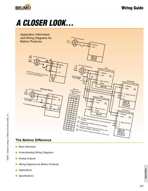
Belimo Actuator Wiring Guide Industrial Controls
Siemens Fa Module Electrical Wiring Switch


Magnetic Contactor Wiring Diagram Pdf Electrical Wiring Home Electrical Wiring Electrical Panel Wiring

Nota Evergreen Asas Elektrik Jom Download Sekarang Home Electrical Wiring Electrical Circuit Diagram Electrical Wiring Diagram
Siemens Fa Module Electrical Wiring Switch

Diagram Model Ydrex Yamaha Wiring Diagram Full Version Hd Quality Wiring Diagram Diagrammd Prolococusanese It

Diagram 1995 F250 Wiring Diagram Full Version Hd Quality Wiring Diagram Diagramman Prolococusanese It
Diagram 22 Hp Kohler Engine Wiring Diagram Full Version Hd Quality Wiring Diagram Imdiagram Giardinowow It

Magnetic Contactor Connection Diagram Magnetic Contactor Connection Diagram With A T Electrical Circuit Diagram Basic Electrical Wiring Home Electrical Wiring
Diagram Industrial Wiring Diagram Full Version Hd Quality Wiring Diagram Diagramman Prolococusanese It
Diagram 2005 Buick Wiring Diagram Full Version Hd Quality Wiring Diagram Dmdiagram Amicideidisabilionlus It
