Signal Isolator Wiring Diagram
Collection of universal turn signal wiring diagram. The second battery will attach to the 2 via a circuit breaker that is rated appropriately for the battery.

Dscl23 01
0-5AAC ISOLATED 4-20mA RECEIVERRECEIVER 0-5mA EXTERNALLY-MOUNTED MINI-CURRENT TRANSFORMER CT ISOLATOR CONVERTER transformer isolation.
Signal isolator wiring diagram. Rv Isolator Wiring Diagram Fusebox And Wires Worry Parliamoneassieme It. Diode isolator Wiring Diagram Cole Hersee 48530 Smart Battery isolator 200a. Diagram Dual Battery Isolator Wiring Full Version Hd Quality Tilediagram Usrdsicilia It.
Assortment of sure power battery isolator wiring diagram. Click on the image to enlarge and then save it to your computer by right clicking on the image. Wiring Diagram for Dispenser Hook Isolation with 240 Vac Dispenser Hook Signal MODEL STP-DHIB.
12 Volt Battery Isolator Wiring Diagram Page 1. August 9 2018. Dual battery isolator schematic.
A wiring diagram is a simplified standard photographic representation of an electric circuit. A wiring diagram is a streamlined conventional photographic representation of an electric circuit. Dual alternator battery isolator wiring diagram.
Single Alternator Battery Isolator Wiring Diagram Car Alternator Car Audio Installation Alternator. If you need to do this regularly you can place. It shows the components of the circuit as simplified shapes and the knack and signal associates in the middle of the devices.
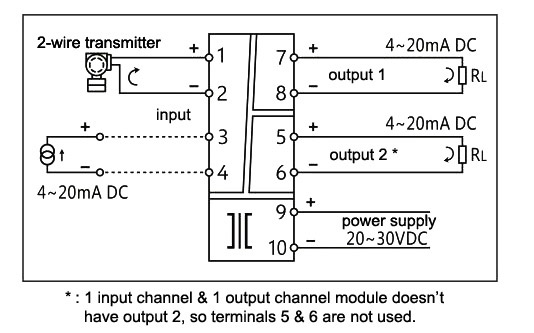
May 9 2018 by headcontrolsystem. Wiring diagram of loop powered isolator with external powered 4-wire transmitter. Turn Signal Wiring Diagram Motorcycle Elegant Wiring Diagram.
It shows the parts of the circuit as simplified forms and the power and signal links in between the tools. Assortment of 3 phase isolation transformer wiring diagram. It shows the components of the circuit as simplified shapes and the aptitude and signal links between the devices.
Discrete input modules discrete input module block diagram powered from the field powered from plc optical isolator provides electrical isolation between field wiring and the plc internal circuitry light emitting diode photoelectric transistor sithcl dswitch closed c tfl th hledcurrent flow through led g t lihtgenerates light lihtti tfl thlight triggers current flow thru pht l tiphotoelectric. SPAN full scale adjust 15 turn. Diode isolator Wiring Diagram wiring diagram is a simplified agreeable pictorial representation of an electrical circuit.
Loop indicator - dim at 4mA bright at 20mA. Connect ground wire to one of the green grounding terminals on the STP-DHI B box. Wiring Diagrams For Turn Signal New Universal Turn Signal Switch.
8 Dispenser Hook Signal terminals are needed see Wiring Diagram 1 for details. 4 20 Ma Transmitter Wiring Types 2 Wire 3 Wire 4 Wire. Single Phase Isolator Wiring Diagram How To Install A Battery Isolator In Your Conversion Van Parked How To Do Connection For Two Pole Mcb Changeover Switch Explain Control Water Heater Using 30 Amp Switch 3 Pole Wiring Diagram Top Electrical Wiring Diagram 3 Pole Wire Diagram Example Wiring Diagram.
Connection Diagrams Front Control Explanation 1. NON-ISOLATED 4-WIRE TRANSMITTER ISOLATED 4-20mA RECEIVER ISOLATOR CONVERTER 24V opto IN isolation Figure 6. The 4 20ma analogue signal is by far the most commonly used in industrial applications.
A wiring diagram usually gives instruction practically the relative slant and. It shows the parts of the circuit as streamlined forms and the power as well as signal connections between the tools. Boat Battery Isolator Wiring Diagram.
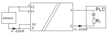
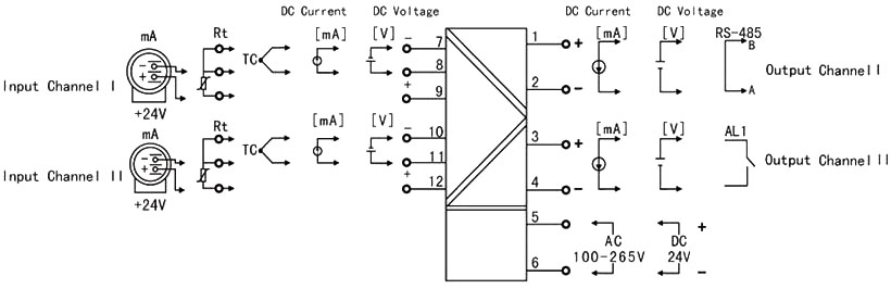
Ac isolator wiring diagram fresh rv battery disconnect switch wiring. 4 20ma transmitter wiring diagram. This is a typical wiring diagram of a loop powered signal isolator get energy from the input and 4-wire transmitter detailed parameters of loop powered signal isolator ATO-S-SINIR-502E are in the product page.
January 9 2020 by larry a. It shows the parts of the circuit as simplified forms and the power and also signal connections between the gadgets. Test socket - output signal access with reference to terminal 1 loop integrity is maintained when digital multimeter Rin.
Attach the cover to the base. Isolator Wiring Diagram Symbol Wires Bacon Parliamoneassieme It. One terminal on the relay should be connected to the positive terminal of the primary starting battery using 6ga red wire.
A wiring diagram is a streamlined conventional pictorial representation of an electric circuit. It shows the components of the circuit as simplified shapes as well as the power as well as signal connections between the devices. An externally-mounted mini-CT steps down a dangerous 0-5 amps AC to a safe 0-5mA AC signal.
Firing Patterns The Closed Loop Circuit Schematic Wiring 7 Loop Powered Signal Isolator Wiring Diagrams Ato Com Wire Light Switch From Schematic Diagram Tips Electrical Light Circuit Diagram Wiring Diagram Symbols And Guide Current Loop Connection Divize Industrial Automation Wiring A Light On Loop Circuit 3 Plate Wiring Diagram. 3 Pole Fan isolator Switch Wiring Diagram wiring diagram is a simplified standard pictorial representation of an electrical circuit. A wiring diagram generally provides details concerning the relative.
Get 4 20ma pressure transducer wiring diagram sample collections of 3 wire pressure transducer wiring diagram luxury great 3 wire sensor. Wiring Example RL is input load of PLC VSD or other process instrument.

![]()
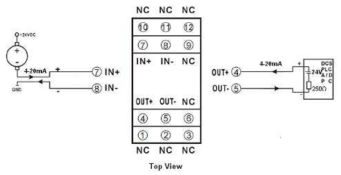
Isolated Transmitter Wiring Examples
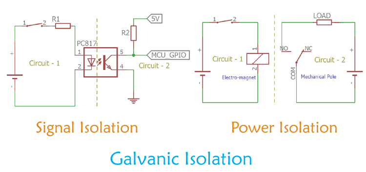
Galvanic Isolation Signal Isolation And Power Isolation
![]()
7 Loop Powered Signal Isolator Wiring Diagrams Ato Com
![]()
7 Loop Powered Signal Isolator Wiring Diagrams Ato Com
![]()
0 10v Isolation Convert Transmitter Analog Input 4 20ma Signal Isolator Current Meters Aliexpress

Hart Signal Isolator Galvanic Isolation Dat511h
Signal Isolators Converters And Interfaces Part 2

Two Wires 4 20ma Passive Current Loop Isolator Iso 4 20ma 4 20ma 0 20ma Isolator Isolation Ic Transmitter Module Dc Dc 4 20ma Isolation Amplifier Data Acquisition Meter Sunyuan

![]()
7 Loop Powered Signal Isolator Wiring Diagrams Ato Com
Signal Isolators Converters And Interfaces Part 1

Passive 4 20ma Signal Isolation Conditioner Din11 Iap 100lp 28 50 Wayjun Industrial Automation 4 20ma To Rs485 Rs 485 To 0 5v Pt100 0 10v Rs232 0 75mv 0 100mv Dc Dc Converter Signal Isolator Conditioner Analog To Digital Converter Dc Dc
2 Wires Loop Powered 4 20ma Signal Isolator Iap100lf 15 50 Wayjun Industrial Automation 4 20ma To Rs485 Rs 485 To 0 5v Pt100 0 10v Rs232 0 75mv 0 100mv Dc Dc Converter Signal Isolator Conditioner Analog To Digital Converter Dc Dc

Stereo Audio Isolator Circuitsarchive

Black Green Two Wire Passive 4 20ma 0 20ma Current Analog Signal Isolators At Price Range 12 00 49 00 Usd Piece In Shenzhen Id 6442214
![]()
7 Loop Powered Signal Isolator Wiring Diagrams Ato Com
Signal Isolator Input Output K B S E Pt100 4 20ma 0 20ma 1 5v 0 10v Ato Com
Signal Isolator 4 20ma With Usb Lcd Display Rs485 Ato Com
Signal Isolator Working Principle Types And Its Applications