Flintec Load Cell Wiring Diagram
Load cells wiring color code transducer techniques six wire cell connection utilcell technical information measurement fault finding group four 6 with usb data full bridge strain gauges troubleshooting guide ip69k washdown indicator reference manual 3 wires project question stainless steel junction box shower diagram types of cable and where to shear beam ts16. These load cells are available with different maximum capacities and include accuracy classifications according to OIML R 60 and or NTEP.

Flintec Load Cell Wiring Diagram
Left click drag or.

Flintec load cell wiring diagram. A load cell scale with test weights or a load cell simulator. Interconnecting cabling - confirm that all relevant pins are used see the wiring diagram at the end of this section. How can you easily check whether a load cell is still operational.
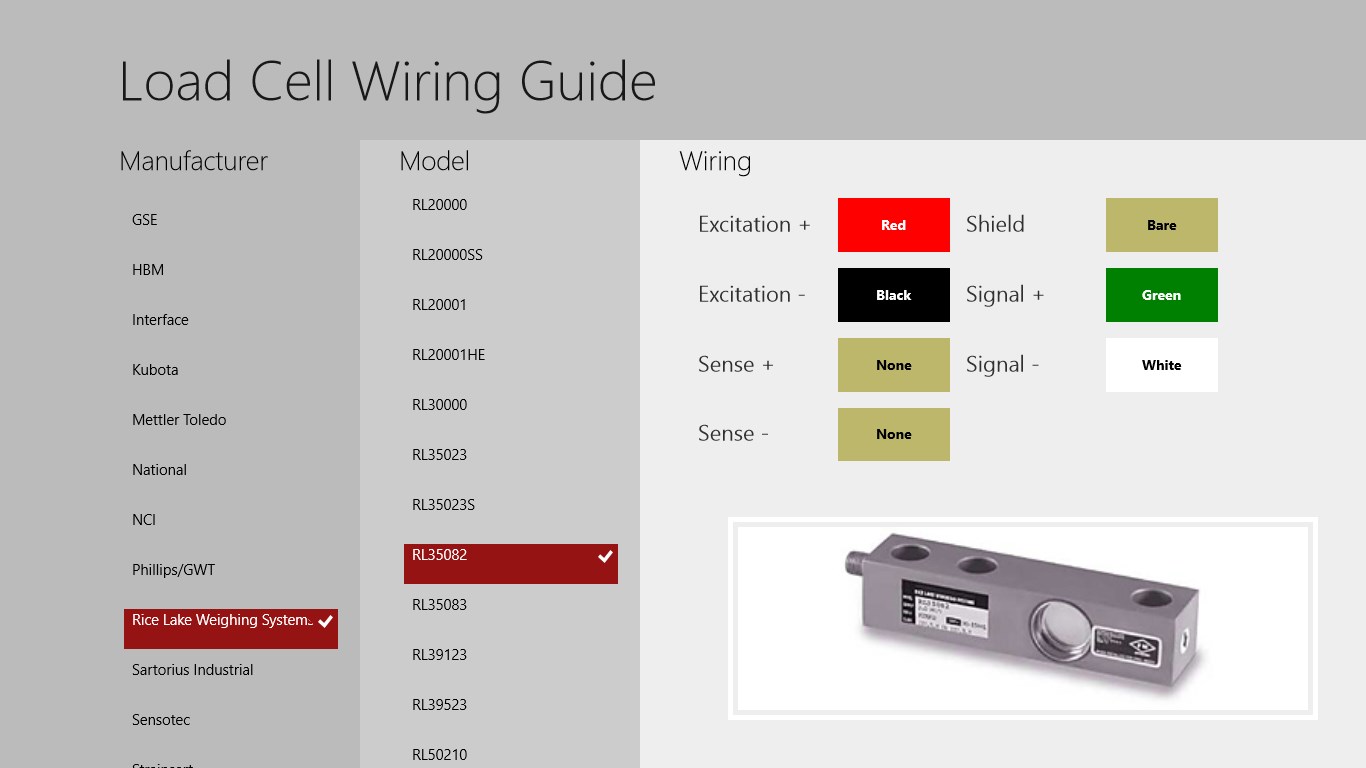
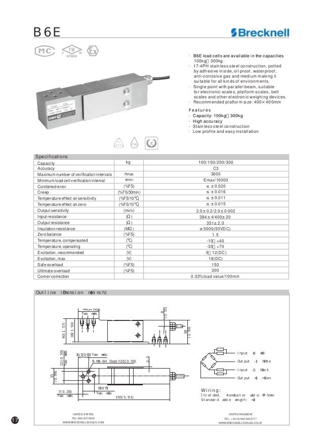
1 Pin numbers indicated in RED text 2 Views show mating faces. 3 m Cable diameter. 5 mm The shield is connected to the load cell body Excitation green Signal white - Excitation black - Signal red Shield yellow.
Eccentric Loading Figure 1-15 This is a condition where the force F is applied vertically to the cell but its line of action is shifted away from the vertical line through. A suitable ASCII communication software. The load cells are admitted only for proper due applications in accordance with the load cell data sheet and Flintec application parts.
The selection of the applied amplifier will be. PC6 Single Point Load Cell 10 - 200kg PC6 - 3D model by Flintec 19b7009 - Sketchfab. A 12-24 V DC power supply capable of delivering approximately 100mA for each LDU and load cell.
Wiring The load cell is provided with a shielded 4 conductor cable AWG 24. 3 m Cable diameter. Interconnecting cabling - See the wiring diagram on Page 6.
Scales And Load Cells Automationprimer Flintec Mettler Toledo Digitol Retrofit Kit Monarch Transducers 2017 Load Cell Catalog 01 01 17 Autosaved Load Cell Wiring Diagram Wiring Load Cell Fault Finding Part 1 Wire Diagram 03 Chevy Avalanche Wiring Library Load Cell Wiring Diagram Wiring Mettler Toledo Multimount Weight Modules Youtube. Our video shows that three test measurements are sufficient to obtain important informatio. The main body and an attached electrical circuit.
One or more LDU 691. Misuse will cause loss of guarantee and manufacturers responsibility. Wiring The load cell is provided with a shielded 6 conductor cable AWG 26.
58 mm The shield is connected to the load cell body Excitation green Signal white - Excitation black - Signal red Shield yellow Sense blue -. Left click drag or. Ture deflection under load and the unavoidable deflection of the load cell itself.
Being Vin the power supply of the bridge or input excitation VVolts and Vout the output signal. Wiring The load cell is provided with a shielded 6 conductor cable AWG 26 or with a shielded 4 conductor cable AWG 24. The main body is what bears the weight or force and accounts for most of the load cells size.
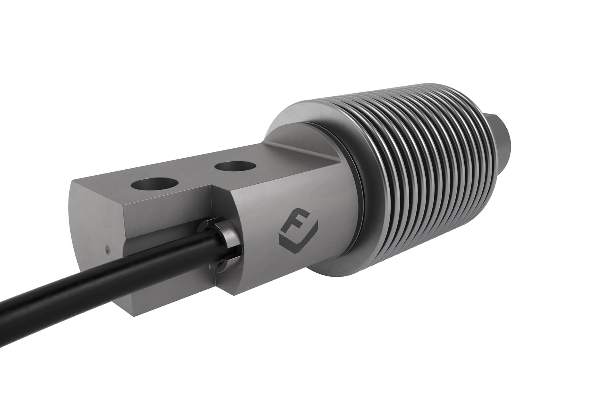
Certifications have been obtained from Weights Measures Authorities worldwide. This arrangement allows to measure very small changes in the resistance R which occurs in the. A typical load cell consists of two parts.
A load cell scale with test weights or a load cell simulator. 5 mm The shield is floating or connected to the load cell body Excitation green Signal white - Excitation black - Signal red Shield yellow. CP-1034-ND locking plug and CP-1234-ND locking receptacle Notes.
Load cell Male CP-1040-ND SD-40 Free-handing Amp box use either Female Female CP-1240-ND SD-40SN Panel mount CP -1140 ND SD 40J Free hanging Alternative. The connection to the PC is carried out by USB or Ethernet interface. Maintenance Maintenance interventions on the load cells are to be carried out only by Flintec.
A load cell is based on an electrical circuit called Wheatstone bridge. SB9 Beam Load Cell 250 - 2000kg SB9 - 3D model by Flintec e3c8948 - Sketchfab. Flintec load cells are designed to be used in various kinds of industrial scales and meet the most stringent accuracy requirements.
3 m Cable diameter. A 12-24 VDC power supply capable of delivering approximately 100mA for each LDU and load cell. Shear Beam Load Cell Ts16.
Typically it is made from high-grade steel or aluminium which ensures mechanical reliability and predictable and. When the scales are based on standard load cells you can select among EM100 or LDUxxx amplifier types which may be plugged into socket within the FlintWeigh III box. 2x type EM100 or LDU digital amplifiers for analogue load cells.

Flintec Load Cell Wiring Diagram Turn Loose The Wedding Ideas
Flintec Slb 25 Klb
Flintec Load Cell Wiring Diagram

2 Load Cell Connection 3 Analogue Output Connection Flintec Faa 26 User Manual Page 9 14
Load Cell Wiring Color Guide Selectiontech


Flintec Dsb7 7 5t Installation Manuallines Pdf Download Manualslib
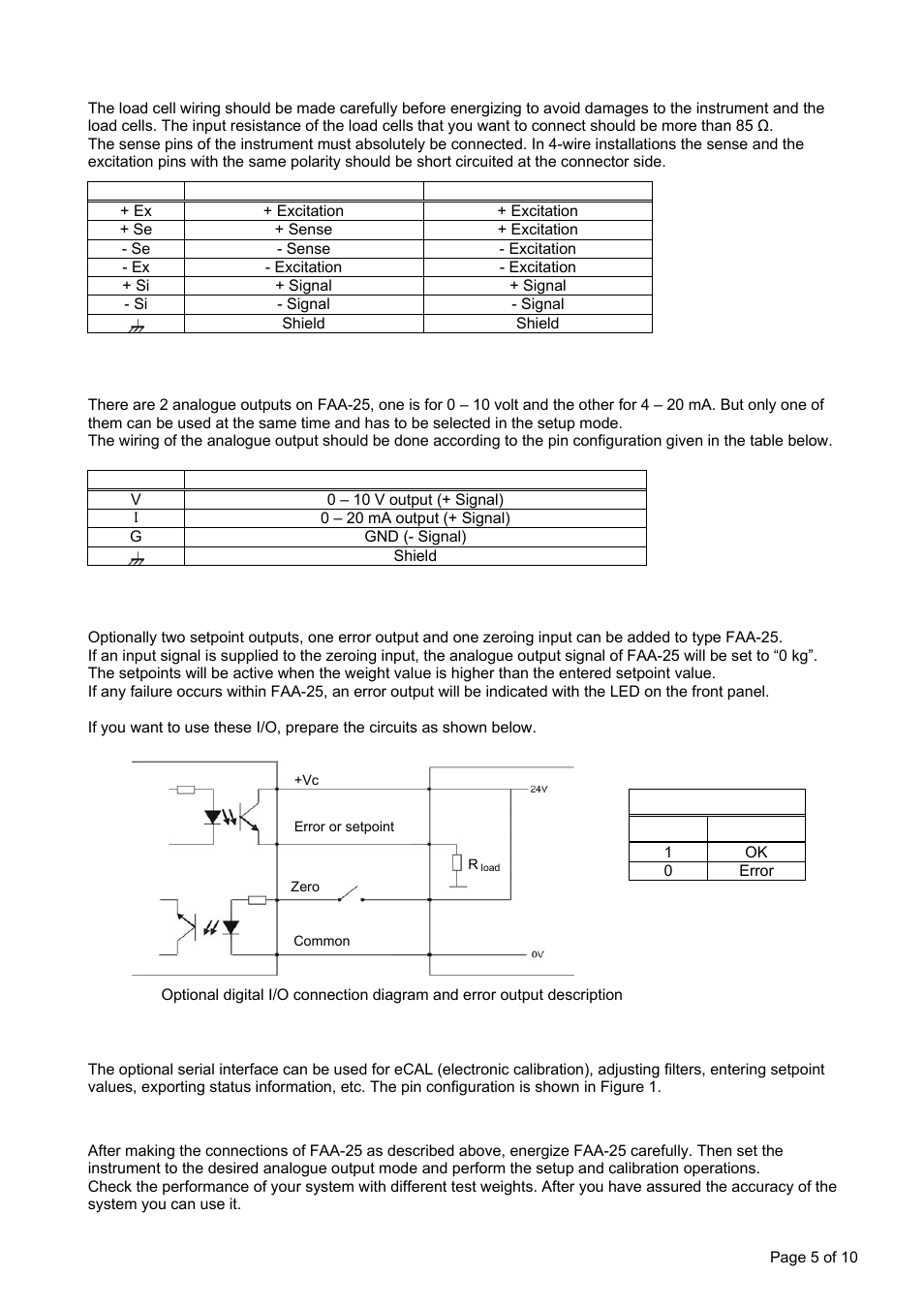
Load Cell Connection Analogue Output Connection Optional Digital Inputs Outputs Flintec Faa 25 User Manual Page 5 10

Flintec Atex User Manual
Sb8 Beam Load Cell 10 500kg Flintec

Flintec

Pc6 Single Point Load Cell 10 200kg Flintec

Flintec Load Cell Wiring Diagram

Flintec Load Cell Wiring Diagram

Flintec Load Cell Wiring Diagram

Flintec Load Cell Wiring Diagram

Flintec Load Cell Wiring Diagram

Flintec Load Cell

C 2 Wiring Diagram 26 C 2 Wiring Diagram Attention Flintec Das 72 1 User Manual Page 26 57
Load Cell Wiring Guide For Windows 10